CNC control: deskproto
By Andres on 6 October 2017
Short introduction guide on how to use the CNC machine at cre-8.
Instructions for CRE-8 CNC
These instructions are based on using expert software of desk proto.
Your model
Your 3D model needs to be stl format, bitmap (png, jpeg, tiff) or dxf
On someone else’s work
Have a look at thingyverse make sure you down load the adequate format.
Starting from scratch 3D model
Use software packages such as FreeCAD and extrude items. Make sure you check the result is a proper STL file: some times you can correct these items Most CAD packages have correctors bundled with in them.
DXF format
You can open these with Inkscape, use the bucket feature to fill in the places where you want material. Use the OPENSCAD addon for inkscape and you will be able to extrude it a certain quantity.
You can import the DXF files directly into deskproto but instead of filling in the material the tool simply follows the paths set by the drawing. (*UPDATE 2018-12-01: recent update fixes this issue)
Hence the recommendation is to use a 3D model just make it as thin as the depth of cut that you want.
Bitmap images
Bitmap images this is possible but note that it will be changed into a grey scale you will then have to fiddle with which colours go up and which go down.
Also note that Bitmap images are by definition pixelated so your resolution will need to be high in order to avoid the result looking like loads of squares.
This facility has not been tested yet.
Importing into deskproto
Load your models into a usb stick and carry it over to the computer next to the CNC machine. Copy it to the documents folder. Delete them after you are finished if you are concerned over IP.
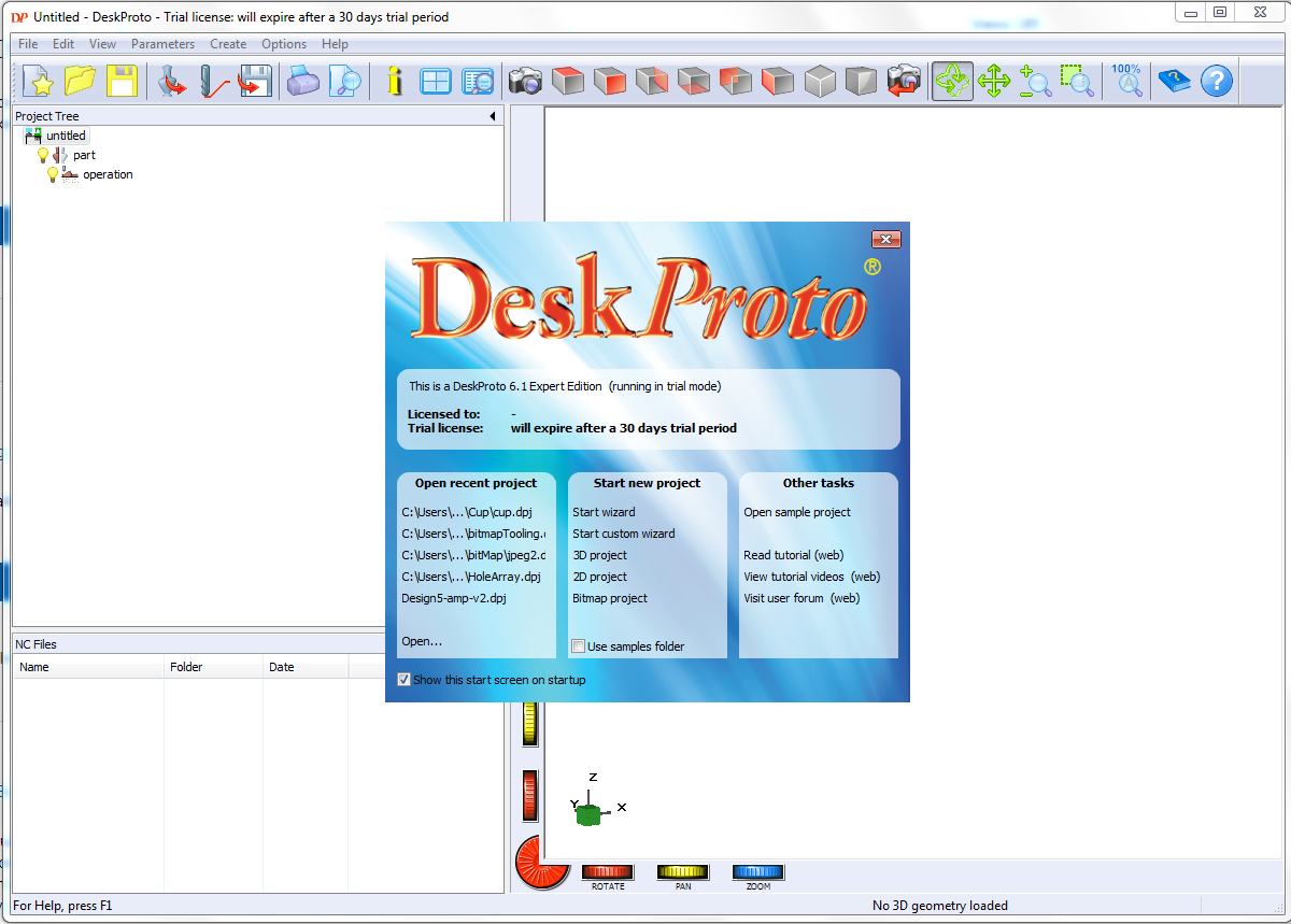
The wizard will help get our figure started with the most basic items, for starters the choice of machine should be the default, if not search through drop down list. Mode will be basic 3D machining. Other items fall out of scope for this section.
Next page of the wizard will ask to load the stl file, you can also scale the the dimensions to adjust for a tool for example. In this case Untick the box that links all the dimensions toguether and choose dimensions. If the material is 1mm thick all round then X and Y should be 2 mm less and Z should be 1 mm less.
Take note of the dimensions loaded. The are shown on the top left window.

These dimensions currently represent the minimum size of material you should use.
The next part of the wizard will let you adjust for your size of the material and the location of the origin. Do note that the relative coordinates are those imported from the original STL file so be aware of this when choosing the workpiece dimensions.

Do note that on the full window the green contour shows the dimensions of the material block from which you are cutting out the part. Deskproto likes to take top surface as a reference. So if you adjust with the detail settings do make note as to the location of the part within the work piece. Also choose the origin, normally bottom left on the left diagram and bottom left again on the right diagram.
Next step is roughing.
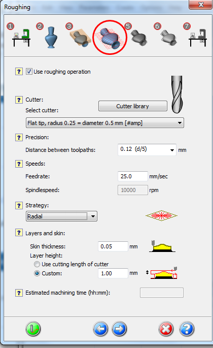
Here the important part is to choose the right cutter. Also it is a good idea to reduce the layer thickness according to what you physically see on your cutter. Do not try to cut more than the actual cutting length of the bit. Change it on the costume field.
Regarding cutting pattern, it depends on the part. If it is circular pattern, it might be useful to use a radial cut as it will probably do the cut faster.
Next stage is finishing.

The current setup will not allow for time for you to change the drill bit mid way. So leave the bit same as above.
The finishing as above depends on your part.
Next stage is contour.

Same cutter for the reasons stated above. This process is optional, if you are planning on doing a subregion of the part, it is not worth having this box ticked.
Final stage on the wizard.
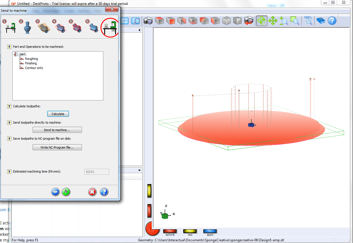
Here you calculate the tool path because finish has many fine steps the figure will be full with red lines.
If you do not want to do a subregion then after calculating you can send to machine.
Ensure that the machine is on, rocker switch will turn green and the green button will need to be pressed as well.
Optional advanced settings.
In the wizard, in the last step before sending the tool path to the machine press the finish flag button on the bottom of the screen.
You will be in the deskproto main window. To the right you see the part with the tool paths in red. If your part has holes it is a good idea to put your sample upside down to see if the tool path goes through the holes.
To the left you will have the project tree, normally you will have the part, roughing stage, finish stage and contour stage which you can delete by right-clicking and selecting delete from the drop down menu.
Another option is operation Parameters
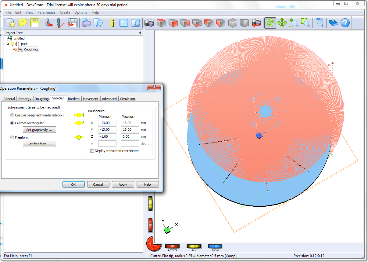
In this case we have picked a sub region to machine. We would recommend the costume rectangular. You can also limit the Z region for cutting. Once you click apply, OK and press the update tool path button the red tool paths will be updated and you will be able to see the areas that will be cut.
To send these tool path to the machine menu> Create > Extra > send current tool path to the machine.
Part loaded on Kay
Kay is the actual program that will send the tool paths to the machine.
You can see the tool path, the white dot is the origin of the part you just imported and red is the location of your cutter.
You now should align the origin of the machine to the origin of the part.
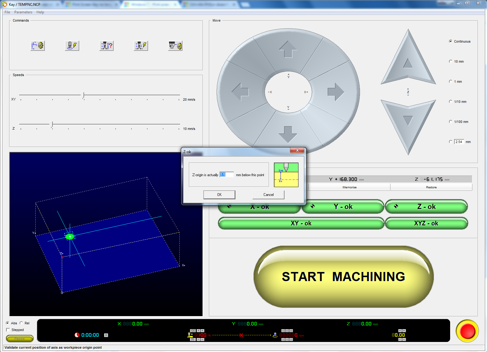
There are different styles of doing this if you have used the same part origins as described above:
- XY coordinate: set the cutter on the back left hand side of the part equivalent to the corner nearest to the router origin (X=0 and Y=0) making the faces tangent to the cutter. Press the green XY OK button.
- Z coordinate to the bottom of the substrate, use a piece of paper to make sure there is at least a bit of friction between the paper an d the bit. Press the green Z OK button and it will pop up with a compensation. If you used the metrobank post its it will be about 0.11 mm bellow your origin.
You can now start machining.
Machining
observe the paths as they are done on the computer model and as they are done on the real part, if there is any concerns you can quickly press spacebar to pause the process and review your tooling.